- 您现在的位置:买卖IC网 > Sheet目录311 > AS1123-BTST (ams)IC LED DVR 16-CH 40MA 24-QSOP
�� �
�
�AS1123�
�Datasheet� -� D� e� t� a� i� l� e� d� D� e� s� c� r� i� p� t� i� o� n�
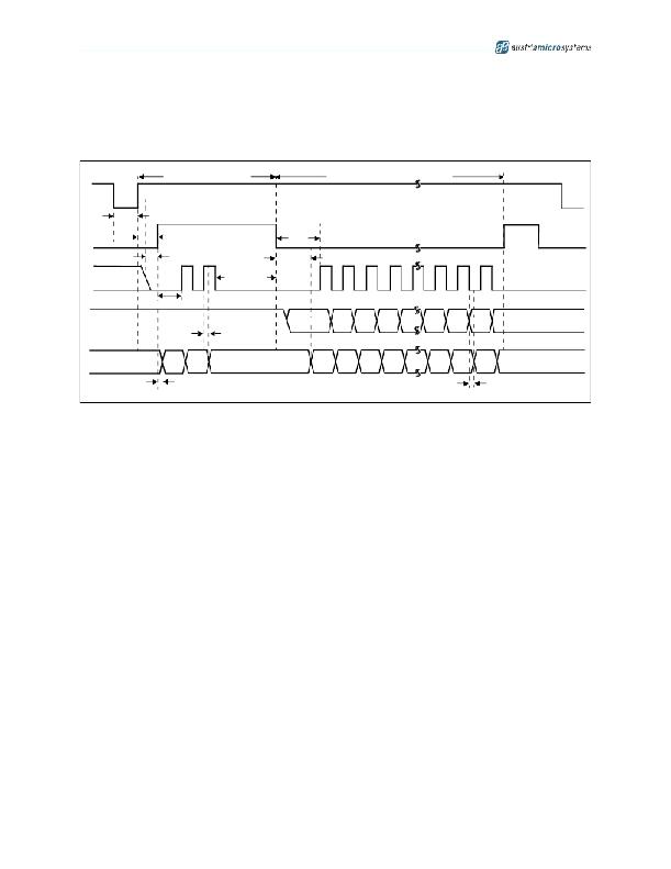
�Detailed� Shorted-LED� Error� Report�
�The� detailed� shorted-LED� error� report� can� be� read� out� immediately� after� global� error� mode� has� been� run� (see� Global� Error� Mode� on� page� 10)� .�
�SDI� must� be� 1� for� the� first� device.�
�Figure� 16.� Detailed� Shorted-LED� Error� Report� Timing� Diagram�
�OEN�
�Global� Flag� Readout�
�t� TESTING�
�Detailed� Error� Report� Readout�
�LD�
�t� SU(ERROR)�
�t� H(L)�
�CLK�
�t� GSW(ERROR)�
�t� GSW(ERROR)�
�t� GSW(ERROR)�
�t� P4�
�SDI�
�DBit15�
�DBit14� DBit13� DBit12�
�DBitn�
�DBit2�
�DBit1�
�DBit0�
�Don’t�
�Care�
�t� SW(ERROR)�
�New� Data� Input�
�SDO�
�T� FLAG� O� FLAG�
�S� FLAG�
�SBit15�
�SBit14� SBit13� SBit12�
�SBitn�
�SBit2�
�SBit1�
�SBit0�
�Don’t�
�Care�
�t� P4�
�Shorted-LED� Error� Report� Output�
�t� P1�
�For� detailed� timing� information� see� Timing� Diagrams� on� page� 8� .�
�Detailed� Shorted-LED� Error� Report� Example�
�Consider� a� case� where� three� AS1123s� are� cascaded� in� one� chain.� A� 1� indicates� a� LED� is� on,� a� 0� indicates� a� LED� is� off,� and� an� X� indicates� a�
�shorted� LED.� This� test� is� used� on-the-fly.�
�IC1:[11111XX111111111]� IC2:[1111111111111111]� IC3:[X100011111111111]�
�IC1� has� two� shorted� LEDs� which� are� switched� on,� IC3� has� one� shorted� LED� switched� off� due� to� input.� 3*16� clock� cycles� are� needed� to� write� the�
�entire� error� code� out.� The� detailed� error� report� would� look� like� this:�
�Input� Data:�
�LED� Status:�
�Failure� Code:�
�1111111111111111�
�11111XX111111111�
�1111100111111111�
�1111111111111111�
�1111111111111111�
�1111111111111111�
�0100011111111111�
�X1� 1� 1� 1� 1� 1� 1� 1� 1� 1� 1� 1� 1� 1� 1�
�1111111111111111�
�Showing� IC1� as� the� device� with� two� shorted� LEDs� at� position� 6� and� 7,� and� IC3� with� one� shorted� LED� at� position� 1.� The� shorted� LED� at� position� 1�
�of� IC3� cannot� be� detected,� since� LEDs� turned� off� at� test� time� are� not� tested� and� will� show� a� logic� "1"� at� the� detailed� error� report.� To� test� all� LEDs�
�this� test� should� be� run� with� an� all� 1s� test� pattern.� For� a� test� with� an� all� on� test� pattern,� low-current� diagnostic� mode� should� be� entered� first� to�
�reduce� on-screen� flickering.�
�Note:� In� an� actual� report� there� are� no� spaces� in� the� output.� LEDs� turned� off� during� test� time� cannot� be� tested� and� will� show� a� logic� 1� in� the�
�detailed� error� report.�
�Low-Current� Diagnostic� Mode�
�To� run� the� open-� or� shorted-LED� test,� a� test� pattern� must� be� used� that� will� turn� on� each� LED� to� be� tested.� This� test� pattern� will� cause� a� short�
�flicker� on� the� screen� while� the� test� is� being� performed.� The� low-current� diagnostic� mode� can� be� initiated� prior� to� running� a� detailed� error� report� to�
�reduce� this� on-screen� flickering.�
�Note:� Normally,� displays� using� such� a� diagnostic� mode� require� additional� cables,� resistors,� and� other� components� to� reduce� the� current.� The�
�AS1123� has� this� current-reduction� capability� built-in,� thereby� minimizing� the� number� of� external� components� required.�
�Low-current� diagnostic� mode� can� be� initiated� via� 3� clock� pulses� during� error-detection� mode.� After� the� falling� edge� of� LD,� a� test� pattern� displaying�
�all� 1s� can� be� written� to� the� shift� register� which� will� be� used� for� the� next� error-detection� test.�
�On� the� next� falling� edge� of� OEN,� current� is� reduced� to� I� LC� .� With� the� next� rising� edge� of� OEN� the� current� will� immediately� increase� to� normal� lev-�
�els� and� the� detailed� error� report� can� be� read� out� entering� error-detection� mode.�
�www.austriamicrosystems.com/LED-Driver-ICs�
�Revision� 1.00�
�14� -� 24�
�发布紧急采购,3分钟左右您将得到回复。
相关PDF资料
AS1390A-ZQFT
IC BOOST CTLR/BUCK CONV 20-QFN
AS212-L
SOCKET 12V AUTO SAFETY CAP MNT
AS212C
AUTO 12V SOCKET W/SAFETY CAP
AS212
SOCKET AUTO LOCKING BLACK
AS3635-ZWLT
IC PHOTOFLASH CHARGER 9WLCSP
AS3642-ZWLT
IC WHITE LED FLASH DRIVER 6WLCSP
AS3643-ZWLT
IC LED DVR CAMERA FLASH 13WLCSP
AS3647-ZWLT
IC LED DVR 1600MA FLASH 13WLCSP
相关代理商/技术参数
AS1123-XXX-I-A1-D
制造商:未知厂家 制造商全称:未知厂家 功能描述:Analog Filter
AS1123-XXX-I-A1-S
制造商:未知厂家 制造商全称:未知厂家 功能描述:Analog Filter
AS1123-XXX-I-A2-D
制造商:未知厂家 制造商全称:未知厂家 功能描述:Analog Filter
AS1123-XXX-I-A2-S
制造商:未知厂家 制造商全称:未知厂家 功能描述:Analog Filter
AS1123-XXX-I-A3-D
制造商:未知厂家 制造商全称:未知厂家 功能描述:Analog Filter
AS1123-XXX-I-A3-S
制造商:未知厂家 制造商全称:未知厂家 功能描述:Analog Filter
AS1123-XXX-I-L-A1-D
制造商:未知厂家 制造商全称:未知厂家 功能描述:Analog Filter
AS1123-XXX-I-L-A1-S
制造商:未知厂家 制造商全称:未知厂家 功能描述:Analog Filter